Tevo Tarantula Hardware Build Guide Overview
Embarking on the journey of assembling a Tevo Tarantula 3D printer can be a rewarding experience, opening up a world of possibilities in 3D printing. This guide aims to provide a comprehensive walkthrough, breaking down the process into manageable steps. Whether you’re a beginner or have some experience, this guide will help you build your own Tevo Tarantula, ensuring you understand each component and step involved. We’ll cover everything from the initial frame assembly to the final calibration and printing of your first 3D model. Follow along closely, and you’ll be printing your own creations in no time. It is important to have a clear understanding of each part before you begin, so take your time and enjoy the process.
Tools and Materials Needed
Before you begin the assembly process, gather all the necessary tools and materials. This will streamline the build and prevent any frustrating delays. You’ll need a set of Allen wrenches (hex keys), a screwdriver set (both Phillips and flathead), wire cutters, pliers, a multimeter (for testing electrical connections), zip ties (for cable management), and a level. Make sure you have a clean, well-lit workspace. Also, ensure all components are present. Refer to the Tevo Tarantula hardware manual or the parts list provided with your printer to confirm that all components are included. Consider having a container or tray to keep screws and small parts organized. Having all necessary tools ready ensures a smooth and efficient build process.
Essential Hardware Components

Understanding the essential hardware components is crucial for a successful build. The Tevo Tarantula typically includes the frame, which is the structural backbone of the printer; the heated bed, which supports the printed objects; the hotend, which melts and extrudes the filament; the extruder, which feeds the filament into the hotend; stepper motors, which control the movement of the axes; endstops, which define the limits of each axis; the control board, which manages all operations; and the power supply unit. It’s essential to familiarize yourself with these components and their functions before you start building. Each component plays a critical role, and understanding their purpose will simplify the assembly process and aid in troubleshooting any issues that may arise. Inspect each part for damage before beginning assembly.
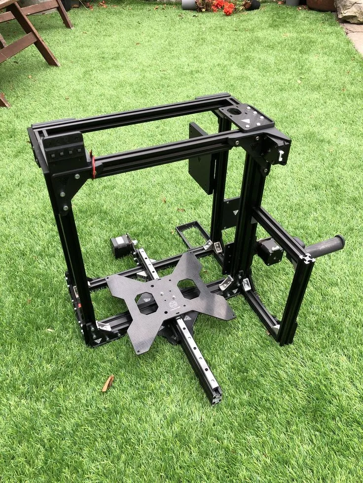
Frame Assembly
The frame assembly is usually the first step in building the Tevo Tarantula. It typically involves connecting the various frame pieces using screws and brackets. Make sure to follow the instructions in the manual carefully, as this ensures the frame is square and stable. Start by attaching the corner brackets to the vertical frame extrusions. Secure the horizontal extrusions to create the base and top of the frame. Double-check the alignment of each part as you go, using a level to ensure that everything is square. Tighten the screws securely, but avoid over-tightening, as this could damage the threads. A solid frame is vital for the printer’s stability and print quality. The frame needs to be solid to ensure a quality print.
Assembling the X-Axis and Y-Axis
The X-axis and Y-axis are responsible for the horizontal movements of the print head and the heated bed. This involves attaching the linear bearings, rods, and belts. For the X-axis, assemble the print head carriage, ensuring the hotend and extruder mount correctly. Then, install the X-axis belt and adjust the tension to the correct level; it should be firm but not overly tight. For the Y-axis, attach the heated bed to the Y-axis carriage and install the Y-axis belt, ensuring it’s properly tensioned. Proper alignment and smooth movement along these axes are crucial for accurate printing. Refer to the manual for specific instructions on belt tensioning and alignment.
Installing the Z-Axis Components

The Z-axis controls the vertical movement of the print head. This step typically involves installing the threaded rods, which are driven by stepper motors, and connecting the Z-axis carriages. Carefully align the Z-axis rods and attach them to the frame. Ensure that the rods move smoothly without any binding. Secure the carriages to the Z-axis rods and attach the bed support structure. Proper alignment and smooth vertical movement are essential for consistent layer adhesion. Make sure the Z-axis components are well-lubricated to reduce friction and ensure smooth operation. Check that the Z-axis moves smoothly through its entire range of motion before proceeding.
Wiring the Electronics
Wiring the electronics can be the most daunting part. However, with careful attention to detail and following the wiring diagrams, you can complete this task successfully. Start by connecting the stepper motors, endstops, hotend, heated bed, and the power supply unit (PSU) to the control board. Use the correct connectors and terminals. Route the wires neatly, using zip ties or cable ties to keep them organized and prevent them from interfering with moving parts. Double-check each connection before powering on the printer. Ensure that all wires are securely connected and that there are no loose connections. Verify the polarity of the connections to prevent damage to the components. Proper wiring is critical for the printer’s functionality.
Connecting the Motors and Endstops
Connect the stepper motors to their respective drivers on the control board. Make sure to follow the control board’s pinout diagram. Then, connect the endstops to the control board. Endstops are sensors that tell the printer when it has reached the end of an axis’s travel. Ensure the endstops are wired correctly so the printer knows where to start. Improper wiring can cause the printer to crash. The order of wiring is very important, so take the time to follow the manual. Test the endstops after connecting them to confirm they are working correctly. Ensure the endstops function as expected.
Wiring the Hotend and Heated Bed

Connect the hotend thermistor and heating cartridge to the control board. The thermistor measures the temperature of the hotend, and the heating cartridge heats the nozzle. Connect the heated bed’s power wires and the thermistor, too. Make sure all connections are secure. Check the wiring diagram again to ensure correct connections. Make sure the hotend and heated bed heaters and thermistors are securely attached. Then, check for any loose wires. Double-check the connections before powering on the printer. Confirm the thermistors are working by monitoring their readings on the LCD panel. Ensure that the heated bed wires are not frayed or damaged.
Software and Firmware Configuration
After assembling the hardware, it’s time to configure the software and firmware. Flash the firmware (usually Marlin or a similar firmware) onto the control board using the Arduino IDE. You’ll need to download the firmware source code and make the necessary configuration changes. This includes specifying the printer’s dimensions, the type of hotend and heated bed, and the stepper motor drivers. Upload the modified firmware to the control board. Connect the printer to your computer via USB, and use a slicing program, such as Cura or Simplify3D, to prepare your 3D models for printing. Configure the slicer settings according to your printer’s specifications and the filament type. Familiarize yourself with the printer’s control panel and settings.
Initial Calibration Steps
Calibration is critical to ensuring high-quality prints. This involves several steps, including leveling the bed and setting the Z-offset. It is important to be patient during calibration. Leveling the bed ensures the first layer of the print adheres correctly. Setting the Z-offset ensures the nozzle is the correct distance from the bed. Perform these steps before every print. Regular calibration is essential for consistent print quality. Use a piece of paper or a leveling sensor to calibrate. The initial calibration significantly influences the quality of your prints. Proper calibration ensures the correct distance between the nozzle and the bed.
Leveling the Bed

Leveling the bed involves adjusting the bed’s height at each corner until the nozzle is the correct distance from the bed surface. There are usually adjustment screws under the bed. Some printers come with an automatic bed leveling system (ABL). Use a piece of paper as a feeler gauge. Move the print head to each corner of the bed and adjust the bed height until the nozzle lightly grips the paper. Repeat this process until all corners are level. Then, start a test print of a single-layer square to confirm the leveling is correct. If the nozzle is too close to the bed, the filament will not extrude properly, whereas if it is too far, the filament will not adhere to the bed.
Setting the Z-Offset
The Z-offset determines the distance between the nozzle and the bed when the printer is at the Z-height zero. This is usually adjusted via the printer’s control panel. After leveling the bed, set the Z-offset by bringing the nozzle close to the bed while the printer is set to home position. Use the printer’s control panel to set the Z-offset. The correct Z-offset will allow the filament to adhere to the bed without squishing the first layer too much. Once you have set the Z-offset, print a test square. If the first layer does not stick correctly or if the nozzle is too close, adjust the Z-offset. Keep adjusting until you achieve the desired first layer adhesion.
Testing the Print
Once the printer is assembled, wired, and calibrated, it’s time to test it. Load your preferred filament, and choose a test print from the SD card, or upload a model via USB. Monitor the first layer closely to ensure proper adhesion. Observe the print for any defects, such as layer shifting, poor layer adhesion, or stringing. Adjust the settings of the slicer and the printer if required. This allows you to refine the settings for your specific printer and filament. If everything is working correctly, your first print should be successful. Keep an eye on your first prints. Adjust the print bed temperature to improve adhesion.
Troubleshooting Common Issues

During the build and initial printing, you may encounter some common issues. If the printer doesn’t power on, check the power supply connections and the fuse. If the motors are not moving, check the motor connections and the motor driver settings. If the hotend is not heating, check the heating cartridge connections and the thermistor. If the prints are not sticking to the bed, make sure the bed is clean, leveled, and the Z-offset is set correctly. Refer to online forums, 3D printing communities, and the manufacturer’s website for troubleshooting assistance. Often, online communities provide solutions to common problems. Document any issues you find and the solutions you use.